KAIRUHS Manual
Hardware v2.2 · Firmware v2.144
Built in the US
Table of Contents
- Introduction
- Kit Overview (Hardware v2.2)
- Power & Flight Controller Integration
- Installation (Displays • LoRa • Sensors)
- Startup Behavior
- Assignable Display Roles
- Configuration (Wi‑Fi Access Point Mode)
- LoRa and FastLink Radar Summary
- Standalone Mode
- Troubleshooting
- Support & Community
1. Introduction
The Kairuhs Kit is a modular telemetry, HUD, and radar system for RC air and ground vehicles. It supports up to four simultaneous displays, each independently assigned to roles like PFD, MFD, HUD, radar, or ground dashboards.
What’s included in this manual
- Hardware v2.2 controller
- LoRa module and Wi-Fi radio behavior
- Light and temperature sensor connections and behavior
- GPS input for standalone mode
- IMU port for factory-installed standalone mode
- PWM input for throttle position
- Firmware v2.144 features and configuration (Wi‑Fi AP UI)
Key capabilities
- Four display outputs with per‑screen role and rotation
- Dedicated LoRa port for peer‑to‑peer radar tracking
- Light sensor for automatic brightness/dimming
- Temperature sensor for ambient or component temps (motor/ESC/engine)
- GPS input port for standalone operation
- IMU port for factory-installed standalone units
- PWM input for throttle position sensing
- MSP and MAVLink protocol support
- Wi‑Fi configuration for all settings; no button module menus
System Modes
Hardware v2.2 supports three operational modes:
- MAVLink Mode: Connect to flight controller via UART for full telemetry
- MSP Mode: Connect to flight controller via UART using MSP protocol
- Standalone Mode: Use GPS, IMU, and PWM inputs without a flight controller (available on factory-configured units)
2. Kit Overview (Hardware v2.2)
Features
- 5V display drive for high outdoor brightness
- Quad display output; assign any role to any of the 4 ports
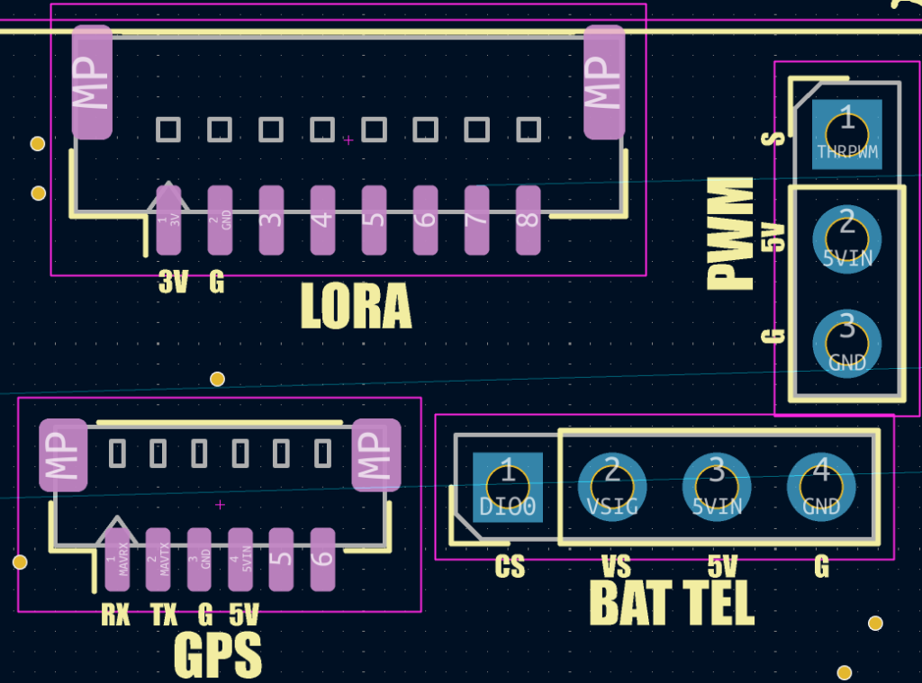
- Dedicated LoRa port for LoRa radar real-time tracking
- Labeled solder pads: 5V • GND • TX • RX for FC UART hookup
- Legacy button menus removed; all setup via Wi‑Fi config
- Light sensor port (4‑pin) for auto‑dimming
- Temperature sensor port (2‑pin) for ambient or component temps
- GPS input port for standalone mode
- IMU port for factory-installed standalone operation
- PWM input port for throttle position
- External Wi‑Fi antenna support (v2.2) for extended range
New in Hardware v2.2
- GPS Port: Accepts GPS input for standalone mode operation
- IMU Port: Factory-installed IMU for standalone attitude reference
- PWM Port: Direct throttle position input via PWM signal
- Reversed Port Orientation: Ports may be reversed compared to previous board versions
Sensors behavior
- Light sensor: Detects ambient light and auto‑dims screens for dusk/night operations
- Temperature sensor: Place on motor, ESC, nitro/gas engine, or use as ambient probe
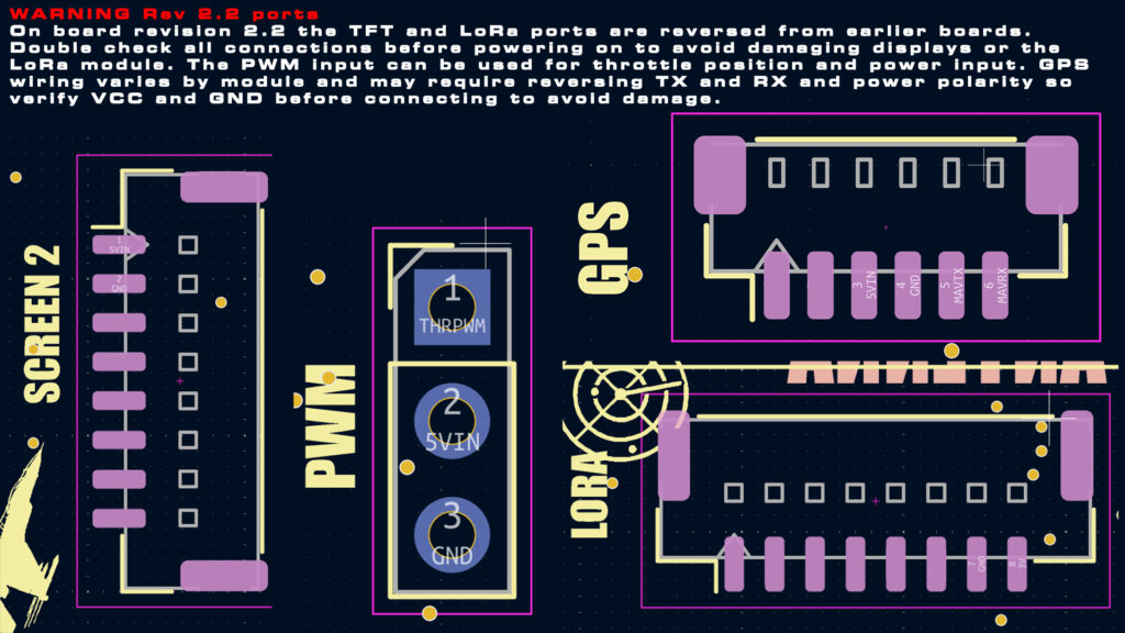
⚠️ CRITICAL PORT WARNING
This warning applies only when mixing different board revisions (v2.0, v2.1, v2.2). All kits come wired and ready to plug and play.
Board v2.2 has reversed port orientation compared to previous versions. Plugging components from older boards into v2.2 with incorrect polarity can result in permanent component damage.
When mixing board revisions:
- Verify the correct port for your component
- Check polarity (VCC and GND positions may be swapped left-to-right)
- PWM and GPS ports are not labeled on v2.2 headers — verify pinout before connecting
- When in doubt, contact support for pinout verification specific to your board revision
Common risks when mixing revisions:
- GPS plugged in with reversed polarity will burn out immediately
- LoRa module in a display port risks damage
- Sensors in wrong ports will not function
If your kit came together in one package, everything is already properly wired and will plug and play.
Caution
Do not mix ports. LoRa must plug into the LoRa port only. Do not insert the LoRa module into a display port. Do not connect FC wiring into sensor ports, or sensors into display/radio ports.
3. Power & Flight Controller Integration
Power sources
The board can be powered through multiple methods. Important: Only use ONE power source at a time.
Power input options (in order of preference):
- FC-IN port (main power input – UART connector with 5V pin)
- Solder pads on the rear of the board (5V and GND)
- PWM port (can be used for standalone mode power)
- USB Port on the main board
⚠️ Power Safety:
- Never power through multiple inputs simultaneously
- Example: If powering through PWM port, do NOT also connect power via solder pads or FC-IN port
- If powering via a source other than PWM port, remove the 5V pin from the PWM connector to prevent conflicts
UART wiring (MAVLink or MSP)
Pin assignments:
- Green → FC RX (connects to FC TX)
- Yellow → FC TX (connects to FC RX)
- Red → +5V
- Black → GND
Protocol settings:
- MAVLink: Baud rate 115200
- MSP: Baud rate 115200
- Make sure ground (GND) is connected along with RX and TX
SpeedyBee F405 Wing / F405 Wing Mini
Plugs directly via the 6‑pin JST UART (TX/RX/5V/GND). No adapters required.
Configuration tip: Confirm the correct UART and set the appropriate protocol (MAVLink 115200 or MSP 115200) under Ports in your flight controller configurator.
INAV Compatibility Note:
- INAV 7.x is the most stable with MAVLink
- MSP works with INAV 7.x and newer
Tested Flight Controllers:
- SpeedyBee F405 Wing / Mini Wing
- ATOMRC NAVI F405
- Skystars F405HD
4. Installation (Displays • LoRa • Sensors)
BOARD 2.2 PIN DIAGRAM
BOARD 2.3 PIN DIAGRAM
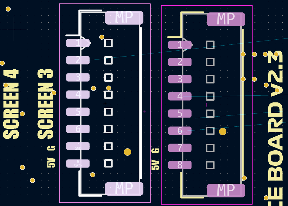
Displays
- Insert 8‑pin cables fully until seated; do not force
- Match orientation: Red = 5V, Black = GND
- Available display types: 1.14″ (ST7789) and 1.44″ (ST7735)
- Display type is configured in the Advanced tab
LoRa Module
- Plug into the LoRa port only
- Never plug into a screen port — this may damage the module
Sensors
- Temp sensor: uses a 2‑pin connector
- Light sensor: uses a 4‑pin connector
- Headers may not be labeled; verify pinout before powering on
- Contact support if uncertain about pin assignments
GPS Input (Standalone Mode)
- Connect GPS module to the GPS port
- Verify polarity before connecting — reversed connection will damage GPS
- Used in standalone mode for position, speed, and heading data
IMU Port (Standalone Mode)
- Factory-installed IMU for standalone attitude reference
- Provides roll, pitch, and yaw data without flight controller
- Only available on standalone-configured units
PWM Input (Throttle Position)
- Connect a Y-splitter from your throttle servo cable
- Provides direct throttle position to the system
- Can power the board through this port
- If powered differently, remove the 5V pin from the PWM connector
5. Startup Behavior
Boot splash shows firmware version (v2.144), followed by system checks.
Status indicators:
- Green = OK, component functioning
- Red = No data or fault detected
System checks (displayed on screen):
- MAVLink/MSP (Flight Controller connection)
- Radio (LoRa module)
6. Assignable Display Roles
Each display (1–4) can be assigned independently in the config. You can duplicate roles across screens and rotate each display individually.
6.1 Primary Flight Display (PFD)
- Speed tape with 3‑second trend vector
- Roll and pitch horizon
- Altitude tape
- Compass and heading (compact or full layout)
- Return‑to‑home arrow and distance to home
- Variometer
- Satellite count; icon turns green at 7 or more satellites
- Selectable units for speed and altitude
6.2 Multifunction Display (MFD)
- Throttle position
- Flight mode display (MAN • ACR • HOR)
- Voltage or fuel‑style gauge
- Current (A) and power (W)
- Battery remaining
- Battery voltage, per‑cell voltage, cell count
- Flap and gear indicators
- Attitude indicators: roll, pitch, yaw
- RC channel mapping: throttle, flight mode, gear, flaps can be assigned to any channel 1–8 and inverted if needed
6.3 HUD Display
- Speed, altitude, pitch, roll, heading
- Distance to home
- Satellite count turns red when no satellites are active
- HUD vertical offset adjustable
- Optional invert for reflective HUD glass alignment
6.4 Air Radar Display
- Live tracking of real and simulated targets
- Circular radar layout with adjustable range and compass ring
- Labels: ID (vehicle or pilot), altitude, distance
- Hostiles show up red
- Top legend: two radio link blocks (LoRa & Wi-Fi) indicate status — green = active, red = inactive; node count shown directly beneath blocks
- Bottom legend: vehicle ID, pilot ID
- Range scaling via transmitter; assign any channel 1–8 and set min/max endpoints in feet
Note: More satellites yield better positional accuracy and visibility on others’ radars.
6.5 Track Dash 1 (Ground)
- Throttle bar segment
- Speed
- Temperature
- Tachometer derived from throttle
- Voltage and arm time
- Shift-light bar LEDs (green → yellow → red) with flashing limiter at the top
Corner LEDs:
- Top-left: Temperature (green, yellow, red, flashing red at critical)
- Bottom-left: Battery (green, red, flashing red at critical)
- Top-right: GPS satellite count (red <7, yellow 7–17, green 19+)
- Bottom-right: MAVLink/MSP activity (green if active, dim if stale)
6.6 Gauges (Ground)
- Voltage gauge
- Temperature gauge
- Fuel level gauge (derived from voltage)
Temperature LED (top-center):
- Dim red = idle
- Solid red ≥ 75 °C
- Flashing red ≥ 85 °C (critical)
6.7 Street Dash (Ground)
- Center: RPM gauge (derived from throttle)
- Right: Speed gauge
- Left: Fuel gauge (derived from voltage), Temperature gauge
- Selectable speed units (MPH / KMH / Knots)
- Theme color applied to all gauge elements
6.8 Radio (Ground)
Touchscreen-style radio with on-timer roll
6.9 Track Dash 2 (Ground)
- Voltage display
- Fuel level (derived from voltage)
- Temperature display with LED indicator
- Satellite count
- Left bar-segment gauge: RPM (derived from throttle)
- Right bar-segment gauge: Speed (up to 55 mph)
- Selectable speed units (MPH / KMH / Knots)
- Theme color applied to gauge elements
6.10 License Plate (Ground)
Plate styles with custom plate text (up to 10 characters)
6.11 Inclinometer (Ground)
Two large gauges:
- Left: Compass
- Right: Attitude (roll and pitch, limited to ±40°)
- Voltage displayed at top
- Speed displayed at bottom
- Theme color applied
6.12 Radar (Ground)
- Landscape square-grid layout with theme-colored grid
- Larger fonts in key areas for readability
- Labels: ID, altitude, distance (same as Air Radar)
- Hostiles show up red
- Same functionality as the circular Air Radar, adapted for ground use
6.13 Double DIN GPS (Ground)
Modern car-style GPS navigation display
Metrics:
- Top right: On time
- Right side (below on time): Speed
- Right side (below speed): Temperature
- Bottom: Satellite count and heading
7. Configuration (Wi‑Fi Access Point Mode)
7.1 Enter AP Mode
- Power on or reset the device and immediately hold BOOT button
- AP instructions will appear on screen
- Connect to the WiFi network shown (default: KAIRUHS_Config, password: kairuhs123)
- Open a browser and go to http://192.168.4.1
7.2 Tabs and Settings
Available tabs: Basics, Gauges, Radio, Ground, Advanced, Manual
BASICS Tab
Warnings
Enable/disable individual warnings and set thresholds:
- Stall
- Overspeed
- Overcurrent
- Low Altitude
- Altitude Ceiling
- Low Voltage
Behavior: Bold red box centered on screen with uppercase label (e.g., VOLTAGE, STALL, ALTITUDE)
Per-screen behavior: Choose which displays show the overlay
- Supported on: PFD, MFD, HUD (Air), Radar (Air)
- Not supported on: Gauges Pages (Air), or any Ground roles
Flash options:
- Select which displays flash during warnings
- Option to flash Air Radar or Air HUD red with warnings, or independently
Units
- Speed: mph, kph, or knots
- Altitude and distance: feet, meters, or yards
Display customization
- Brightness: 1–10
- PFD compass layout: compact or full
- MFD fuel gauge mode: voltage or fuel bar
Identity and labels
- Vehicle ID: 4 characters
- Pilot ID: 4 characters
- Team selection: 1 or 2
Radar label and display toggles
- Radar range
- Show ID label
- Label source: pilot or vehicle
- Show altitude
- Show distance
- Visibility filter: Friends / Foes / All / None
- Eject factor: 1.0 ejects at edge, 1.2 ejects slightly past
GAUGES Tab
Choose across air gauges on multiple screen pages. Tune positions, face size, and page locations.
Available gauge types:
- Airspeed (IAS): Forward speed using 3D ground speed. Units follow Speed Units setting (MPH/KMH/Knots).
- Altimeter: Altitude display. Units follow Alt/Dist Units setting (Feet/Meters/Yards).
- VSI (Vertical Speed): Climb/sink rate. Units follow altitude units setting.
- Turn Coordinator: Bank/roll indicator with realistic slip ball physics.
- Heading: Compass heading indicator.
- RPM: Derived from throttle position with smoothing for realistic behavior.
- Manifold Pressure: Simulated from throttle position and current draw.
- Oil Pressure: Simulated from throttle and amp draw with realistic dynamics.
- Oil Temperature: Simulated from throttle, current draw, and airflow (3D ground speed). Scale: 0–300°F with green/yellow/red bands.
- Fuel Quantity: Based on per-cell voltage (total V ÷ cell count). Maps ~3.30–4.20V to 0–100% with left/right mirror needles.
- Coolant Temperature: Simulated from throttle, current draw, and airflow (3D ground speed). Scale: -50–150°C.
- Attitude (AHI): Classic blue/brown artificial horizon with roll and pitch. Includes dim mode for lower brightness to match ambient lighting.
- Mono AHI (Page 4): High-contrast monochrome artificial horizon for clean, low-glare layouts.
- Gear Indicator (Page 4): Shows gear state with color logic (Green = Up, Red = Down). Gear channel assignment configured in Advanced tab.
- Flaps Gauge (Page 4): Flap angle indicator with color logic (Green = 0°, Yellow = 20°, Red = 40°). Flaps channel assignment configured in Advanced tab.
- Battery Voltage Gauge (Page 4): Segmented red/yellow/green arcs that flash when voltage crosses warning threshold (set in Basics tab).
Gauge Positioning:
- X coordinate: Left to right (increasing X moves right)
- Y coordinate: Up to down (increasing Y moves down)
- Page: Set to 1, 2, 3, or 4 (only gauges matching active page render)
- Face size: Diameter in pixels (typical range 30–120px)
Theme Color: All gauges follow your selected global Color Theme for needles, arcs, bands, and markings. Changing the theme updates every gauge instantly.
Artificial Horizon Dim Mode: The Attitude (AHI) gauge can be bright in low-light conditions. Enable Dim Mode to tone down the colors for better ambient matching.
RADIO Tab
The platform supports two radios: Wi-Fi (high-speed/mid-range) and LoRa (mid-speed/long-range). These may be used independently.
⚠️ Note: Hybrid mode is currently in development and not available in this firmware.
Master Radio Status
- 0 — Off: All radio systems disabled
- 1 — Wi-Fi: Wi-Fi telemetry only
- 2 — LoRa: LoRa telemetry only
Wi-Fi Settings
- Channel: US: 1–11. Choose a quiet channel if interference appears.
- TX Power: Adjustable output. High TX power may increase noise or cause SPI instability.
- Long-Range (LR): Optional extended-range mode. Verify local regulations.
⚠️ Power Warning: High TX power can potentially cause SPI communication issues, especially when using multiple ST7789 panels. If experiencing screen corruption or instability, try reducing TX power.
LoRa Settings
- Region: US (902–928 MHz), EU (863–870 MHz), or Custom
- Center Frequency:
- US: 915.0 MHz
- EU: 869.5 MHz (common)
- Bandwidth:
- EU: 125/250 kHz
- US: may use 500 kHz
- TX Power: Adjustable. Antenna required before transmitting.
⚠️ Antenna Warning: Never transmit without a properly matched antenna.
Quick Band Hints
US (FCC): 902–928 MHz ISM. 500 kHz permitted.
EU (RED): 863–870 MHz:
- 868.0–868.6
- 868.7–869.2
- 869.4–869.65
Tip: 869.5 MHz is a common EU selection.
On-Screen Indicators
Two blocks show link status:
- Green = active
- Red = inactive
Node count appears below these indicators.
Compliance
Users are responsible for ensuring regulatory compliance in their region. Follow local laws regarding frequency, power, and duty cycle.
Troubleshooting
- No targets shown: Verify radio mode, antenna connection, region/BW match, and visibility filters
- Unstable behavior: Lower TX power, confirm antenna load, verify power supply stability
- All devices must share identical LoRa parameters: region, frequency, bandwidth, spreading factor
GROUND Tab
Speed Units
- MPH / KMH / Knots — applies to all ground screens showing speed
Dash Theme
- Primary Theme Color: Sets accent color for gauges, bars, and legends
- Text Color: Sets text color for ground dashboards
- Ground Radar Theme Color: Sets grid and accent colors for Ground Radar
Roles
Assign what each screen shows while in Ground mode:
- AIR pages: PFD, MFD, HUD, Air Radar, Gauges Page 1–3
- GROUND pages: Street Dash, Track Dash 1, Track Dash 2, Ground Gauges, Radio, License Plate, Inclinometer, Radar (Ground), Double DIN GPS
Display/rotation constraints:
- 1.44″ screens can show AIR pages in any orientation
- 1.14″ screens can show AIR pages in portrait only
- GROUND pages require landscape orientation
RC Mapping
- RC Throttle Chan / Invert: Maps RC channel for throttle-derived features (RPM bars) with inversion option
- Throttle Bottom (%): Trims low end so brake doesn’t register as throttle
License Plate (Ground)
- Plate Text: Custom text up to 10 characters
- Plate Type: Choose style (CA Classic Blue, Digital CA, Canada, etc.)
ADVANCED Tab
System Mode
- MAVLink: Connect to FC via UART for full telemetry (baud 115200)
- MSP: Connect to FC via UART using MSP protocol
- Standalone: Use GPS, IMU, and PWM without flight controller (factory-configured units only)
Display Speed and Screen Management
Disabling unused screens can increase CPU speed, reduce CPU load, and increase frame rate. Using only 1-2 screen ports can speed up the system by 2x-3x.
Display Refresh Rate:
- 16 MHz: Most stable, slowest refresh
- 20 MHz: Balance between speed and stability
- 27 MHz: Default setting
- 40 MHz: Advanced users, may cause issues on some setups
- 80 MHz: Maximum speed, use with caution
Stability Guidelines:
- Lower speeds = more stable
- Higher speeds = faster refresh but potential for screen tearing, corruption, black screens, or freezes
- ST7789 (1.14″) displays are more sensitive to high speeds
- ST7735 (1.44″) displays are more stable
Displays & Rotation
Display Type:
- 0 = ST7735 (1.44″, 128×128)
- 1 = ST7789 (1.14″, 135×240)
Screen Rotation: 8 modes: 0°, 90°, 180°, 270° and their mirrored variants
Display/rotation constraints:
- 1.44″ screens: AIR pages in any orientation
- 1.14″ screens: AIR pages in portrait only, GROUND pages require landscape
Roles
Assign what each screen renders in AIR or GROUND contexts. Roles saved per slot (Screen 1–4):
AIR roles:
- PFD, MFD, Radar (Air), HUD, Gauges Page 1, Gauges Page 2, Gauges Page 3
GROUND roles:
- Track Dash 1, Track Dash 2, Street Dash, Ground Gauges, Radio, License Plate, Inclinometer, Radar (Ground), Double DIN GPS
HUD Vertical Offset
Shifts the HUD up/down. Range: 0–112
RC Mapping (Chan/Invert)
Displays current RC channel mapping and inversion flags for:
- Flaps
- Gears
- Flight Mode
- Throttle
Use these to verify inputs used by dashes/gauges.
TX Adjustable Radar Range
- Enable (0/1): Turn channel-based range control on/off
- Channel (1–8): RC source used to scale range
- Invert (0/1): Flips channel sense
- Bottom/Top (ft): Min/max feet for mapping (values align to 25 ft steps)
When enabled, visible radar radius maps to selected RC channel between Bottom–Top.
TX Screen / Role Switching
Control how screens switch and cycle roles using transmitter.
Inputs:
- Screen Select Channel: Chooses active screen
- Role Cycle Channel: Cycles through enabled roles on selected screen
- Default Screen: Used when no Screen Select channel assigned
Per-Screen Role Enable/Disable: Each screen includes checkboxes to disable roles you don’t want screens to switch into during operation. Only enabled roles included when cycling mid-flight or mid-drive.
Simulation
- Sim Enabled (0/1): Master toggle
- Spawn Chance %: Probability per tick for new sim target
- Max Sims on Radar: Cap on concurrent simulated targets
- Pursuers Enabled (0/1): Allow chase logic
- Pursuer Chance %: Probability new sim is pursuer
- Show Sims Mode: All / Friendly / Hostile / None
- Friendly Pursuer %: Likelihood pursuer is friendly
- Pursuit Aggressiveness (1–10): Higher = tighter turns/closing behavior
- Follow Distance (ft): Nominal spacing for followers
- Min/Max Chase Speed (ft/s): Speed band for pursuit logic
- Vertical Gain (ft/s per ft): Climb/sink response to altitude error
Save Behavior
Use Save Settings at the bottom of the page to write changes. The device reboots into normal mode with the new configuration.
8. LoRa and Wi-Fi Radar Summary
Real-time peer-to-peer radar tracking for nearby targets in air and on ground. Supports up to about 15 pilots. Higher network congestion reduces update rate.
Indicative range (HW v2.2 with external antennas):
- Ground → air: ~1500 ft @ 20 Hz (typical)
- Air → air: often farther
Display features:
- Circular air radar and landscape square-grid ground radar
- Target labels: ID, altitude, distance
- Hostiles show up red
- Top legend: radio status (green = active, red = inactive), satellite count, current radar range
- Bottom legend: vehicle ID, pilot ID, radio node presence
Note: More satellites yield better positional accuracy and visibility on others’ radars.
9. Standalone Mode
Standalone mode is only available on factory-configured units with pre-installed IMU.
Requirements for Standalone Operation
With only the board, you get basic orientation data. For full functionality:
Required connections:
- GPS module → GPS port (provides speed, heading, position)
- PWM throttle cable → PWM port (provides throttle position)
- Power → FC-IN, solder pads, or PWM port (choose ONE source only)
Setup and Safety
⚠️ Critical:
- PWM and GPS ports are not labeled on v2.2 headers
- Verify pinout before plugging in and powering
- Board can be powered through PWM port
- Never power through multiple ports simultaneously (e.g., solder pads AND PWM port)
10. Troubleshooting
No MAVLink/MSP Data
- Verify TX and RX are not reversed
- Check baud rate: 115200 for both MAVLink and MSP
- Confirm correct UART in flight controller configurator
- Ensure ground (GND) connection along with RX and TX
- Try INAV 7.x if using INAV with MAVLink
No Radar Targets
- Ensure radio module is connected and enabled in Radio tab
- Verify radio settings match other pilots/drivers (channel, bandwidth, frequency)
- Check visibility filters (Friends/Foes/All/None)
- Confirm antenna is properly connected
Blank Display
- Confirm correct display driver (ST7735 or ST7789) in Advanced tab
Display Issues: Screen Tearing, Corruption, Black Screens, Color Shifting
These issues particularly affect ST7789 (1.14″) displays and can be caused by:
Common causes:
- High SPI speed
- Radio transmitting
- Insufficient power supply
Systematic Troubleshooting:
- Start with minimal configuration:
- Disconnect all modular components: LoRa, temp sensor, light sensor
- Test with one screen only
- Test each display individually
- Test each port individually
- Swap cables and displays to identify weak components
- Add components incrementally:
- Once one screen works, add another
- Continue adding until corruption appears
- Identify the threshold where problems begin
- Firmware tuning:
- Lower SPI speed (most effective solution)
- Start at 16 MHz for maximum stability
- Gradually increase if needed
- 27 MHz is the default setting
- Disable unused screens to reduce CPU load
- Hardware solutions:
- Extend TFT cables (may help reduce EMI)
- Keep cables away from antennas and 2.4 GHz receivers (ELRS, Spektrum)
- Add capacitor to power input pads (may help stabilize power)
- Try different flight controller if available
- Radio considerations:
- Reduce TX power
- High TX power draws more current and can cause SPI issues
- Radio off = more stable displays
- Power considerations:
- USB power with multiple displays almost always causes issues
- Use external 5V supply for best results
- Adequate power supply is critical with multiple screens
- Display considerations:
- ST7735 (1.44″) displays are more stable and rarely show issues
- ST7789 (1.14″) displays are more sensitive to EMI and power issues
- Consider using ST7735 displays if experiencing persistent problems
If problems persist:
- Contact support
- Troubleshoot thoroughly first before requesting replacements
- Provide detailed information about testing performed
Tested configurations:
- Speedybee F405 Wing/Mini Wing: All 4 screens work with radio inactive
- ATOMRC NAVI F405: Verified working
- Skystars F405HD: Verified working
- Extending screen wires helps reduce interference
- Proper cable routing away from antennas is essential
11. Support & Community
Email: kairuhsconsole@gmail.com
Thingiverse: https://www.thingiverse.com/kairuhshq/designs
Facebook: https://www.facebook.com/groups/1231576258453632/
YouTube: https://www.youtube.com/@Kairuhshq
Instagram: https://www.instagram.com/kairuhshq/
Recommendations & Requests
Suggestions for new screen types or specific PFD/MFD layouts are always welcome. Share your ideas via email or social media — we consider all submissions for future updates.
We improve the platform through community feedback. Send build photos, flight footage, and notes; we may feature your work.
Thanks for flying KAIRUHS. Fly low. Fly fast. Fly smart.
Manual version: Hardware v2.2 · Firmware v2.144
Last updated: February 2026